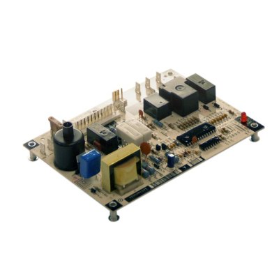
Carrier Furnace Control Boards LH33WP003 Ignition Control Module
Carrier Furnace Control Boards
Designed to meet exact Carrier® Corporation specifications, ensuring optimum system performance, proven reliability, easy installation and maintenance and safe system operation
Please Visit Our Store or Call us with questions. Thank you!
Description
Carrier Furnace Control Boards
Description
Factory Authorized Parts are designed to meet exact Carrier® Corporation specifications, ensuring optimum system performance, proven reliability, easy installation and maintenance and safe system operation.
| Dimensions | |
|---|---|
| Length | 5.9843 Inches (in) |
| Width | 7.7165 Inches (in) |
| Height | 1.5748 Inches (in) |
| Weight | 0.55 Pounds (lbs) |
| Attributes | |
| Brand | RCD Parts |
| CSA Listing | Yes |
| Country Of Origin | CAN |
| Cubic Measurement | 0.0421 |
| Cycle/Hertz | 50/60 Hz |
| Dimensional Weight | 1 |
| EAN | 0662441371639 |
| Module Type | Ignition Control Module |
| Prop 65 | No |
| UOM | EA |
| UPC Barcode | 662441371639 |
| Voltage | 208-230 VAC |
Installation Instructions
1. Turn thermostat to OFF position or set it to the lowest possible setting.
2. Turn OFF electrical supply to furnace.
3. Turn OFF gas supply to furnace. CAUTION! Failure to turn off gas and electric supplies can result in explosion, fire, death, or personal injury.
4. For 80% furnaces, remove control access and blower door; for 90% furnaces, remove outer door assembly and remove the two screws from blower access panel and set aside.
5. Disconnect thermostat wires and humidifier wires (if equipped with a humidifier).
6. Disconnect line voltage, blower, electronic air cleaner wires (if equipped), and transformer wires.
7. For 80% furnaces, remove retaining screws and remove furnace control board from bracket; for 90% furnaces, remove two screws from blower deck that hold the control box assembly. Lower the control box assembly. Remove retaining screw(s) from board and remove board from control box assembly.
8. Remove wiring harness connectors from circuit board.
9. Examine control and control box to check for water stains.
10. Make repairs if any sources of water leakage are found. Be sure to check humidifiers, evaporator coils, and vent systems in the area of the control.
Step 2: Install the New Control
1. Ground yourself. When handling circuit board, hold it by the edges.
2. Insert tab(s) of board into the slots of the control box (if required).
3. Fasten circuit board with retaining screw(s). Install the included wiring harness adapter to the three connections of the existing furnace wiring harness. A. The furnace harness 9-pin connector plugs into the mating 9-pin adapter harness connector.
B. The furnace harness 2-pin connector plugs into the mating 2-pin adapter harness connector.
C. The furnace harness 3-pin connector plugs into the mating 3-pin adapter harness connector.
4. Connect the other end of the included adapter harness to the new furnace control board.
A. The 11-pin connector connects to PL1 on the furnace control board.
B. The 2-pin connector (with 2-black wires) connects to PL2 on the furnace control board.
C. The (2) white wires connect to the 115-volt Neutral spade connections located in front of PL1 on the new furnace control board.
System Tests Step 1: Component Self Test 1. Begin component test sequence by ensuring that thermostat is turned to OFF position and thermostat wires are disconnected. Turn power ON and manually close the blower door switch. With a short piece of wire, briefly short TEST/TWIN terminal to Com/24V terminal. The component test sequence follows:
A. Status LED will flash code and will then turn ON the inducer motor.
B. Inducer motor will run for the entire component test.
C. Hot surface ignitor will turn ON for 15 secs.
D. Blower motor heat speed will turn ON for 10 secs.
E. Blower motor cool speed will turn ON for 10 secs.
2. Repair, replace, or service any failing components from the component self test. The gas valve is not energized during the self test.
3. Turn power OFF.
4. Release the blower door switch. Twinning Instructions A 3/16” quick connect terminal is provided on the ICM282B control board for communication between another ICM282B control board for furnace twinning.
To configure your control boards for twinning:
1. Install each control board according to the installation instructions.
2. Connect the TWIN terminals together.
3. Connect the 24 VAC common together. (A common ground between the two furnaces is also required.) If the 24 VAC supplies to the control are in phase, both furnaces will turn the blower on and off synchronously and at the same speed. If the 24 VAC supplies are not in phase, then neither control will respond to the thermostat commands and the status LED will flash rapidly.
Only logged in customers who have purchased this product may leave a review.


Reviews
There are no reviews yet.